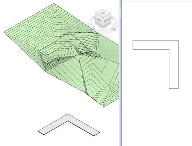
Back in July, I posted about the Topo Align app, which is a great little app that you can download from the Autodesk app store, for only $1.99. It has three tools that all modify Topography, including the main tool, Align to Element, which aligns Topo to an edge or set of faces (like a Shape-Edited Floor).
And it is an awesome (and very affordable) app. However, it only aligns Topo to Hardscape. What if you need to align Hardscape to Topography? Turns out, you can do it in Dynamo…
To start out, you will need to install the Clockwork Package, by Andreas Dieckmann. To do this Open Dynamo, go to Packages, Search for a Package…
And download the latest version of Clockwork (right now it is 0.7.x)
In Revit you will need to have a Floor, a Toposurface, and a Subregion with the same boundary as the Floor. The Subregion can be created very quickly by tracing the Floor boundary.
And back in Dynamo, all you need is this very simple definition:
BUT, be sure that you run it in Manual mode. Apparently something about the Select Model Element(s) nodes requires a Manual run.
And, Voilà! You have a shape edited Floor that follows your Topography perfectly.
And, in section:
Additional Notes
The Floor can be hosted to any Level and at any offset, however if you want the sub-element points to match absolute elevation, host the Floor at Sea Level with no offset.
Graphically, it looks best if you leave the Subregion. If the Subregion is deleted, then the Floor will overlap more with the main Toposurface:
If you leave the Subregion, you can also just hide it in any views where you don’t want to see any overlap.
The Subregion is actually critical for getting all of the necessary points. If you try to run the definition with the Main Surface, you will not get all of the points, and it is possible the Floor might not shape-edit at all.
And any Floor with a curved edge is probably going to generate a lot of points.
But you can simplify the Floor by deleting points. In fact, you can select and delete all of the points, though the Floor will keep all of the essential boundary points.
Obviously, the Floor is no longer following the Topo perfectly, but sometimes you might just want a close approximation.


Looks great in the abstract example, but a shame it uses subregions – they’re so slow and unreliable and boundaries between them never work, even when you copy-paste the same sketch lines.
I agree Subregions are highly unstable- they always think they overlap when they really don’t. However, this is the most use I’ve ever gotten out of a Subregion. Another option would be to split the Surface, but that makes a mess and is quite difficult to manage. You can always delete the Subregion- it’s really not necessary.
This really looks like a useable function! Slightly related, do you have any input on best practice when importing material from a road engineer? I’m working in a project where we can get a 3D dwg file of the road, but when I make a toposurface from it, it doesn’t follow the contour lines at all times and the dwg lines seems to be slightly above the topo. At some points it differs as much as 80 mm, which isn’t really acceptable. The 3D lines in the dwg file consists of many small segments, around 500 mm each. I’ve tried to import it as a road LandXML using the Roads & Terrain extension, but the LandXML files I get from the road engineer don’t work.
Any input on this would be greatly appreciated.
Do you only have the contour lines? If possible, it would be better to get a points file or a TINN of the surface. Or if you have access to Civil 3D you could create your own surface. I’m not sure about the LandXML import options, I haven’t used them before.
Thanks for the input! I only have contour lines now but I can ask for points or a TINN. The file isn’t exported from Civil 3D but from Novapoint, an Autocad add-on.
A little update on this: I got a TINN of the surface from the road engineer, which worked much better when converting to a Revit topo. The surface seems to follow the linked file now. Thanks again!
Glad to hear it. Because of how Topo is generated, a TINN will almost always create a better surface than contour lines.
I tried your workflow and got no result in Revit. The floor did not change to fit the subregion for some reason…
Am I doing something worng?
Hi Eyal, it is a very simple definition, so there is not much room for error. Make sure that the subregion and floor have the same boundary in plan. Also, make sure that you have the correct Clockwork package installed- it will vary depending on your version of Dynamo. I am running Dynamo 9.2 and 1.0 with Clockwork 0.90.7.
Nice little graph. How do you deal with the edges of the floor? The four corners of the floor connect to each other which creates a thin slab edge that appears as a straight line between the corners from the elevation of the topography that they find. I am using a newer versions of clockwork so I am using the Floor.SlabShapeByPoints node.
I’m not sure what you mean by ‘deal with the edges of the floor’… make sure the subregion boundary matches the floor boundary, otherwise the floor edges might not match correctly.